Two sensors for measuring distance with the Arduino are extremely popular: the infrared proximity sensor and the ultrasonic range finder. They work in similar ways and achieve pretty much the same thing, but it’s important to pick the right sensor for the environment you’re in.
An infrared proximity sensor has a light source and a sensor. The light source bounces infrared light off objects and back to the sensor, and the time it takes the light to return is measured to indicate how far away an object is.
An ultrasonic range finder fires out high frequency sound waves and listens for an echo when they hit a solid surface. By measuring the time that it takes a signal to bounce back, the ultrasonic range finder can determine the distance travelled.
Infrared proximity sensors are not as accurate and have a much shorter range than ultrasonic range finders.
Consider the following during planning:
Complexity: Both of these sensors are designed to be extremely easy to integrate with Arduino projects. In the real world, they’re used for similar electronics applications, such as proximity meters on the back of cars that beep as you approach the curb. Again, the main complexity is housing them effectively.
Infrared proximity sensors such as those made by Shape have useful screw holes on the outside of the body of the sensor. Maxbotix makes ultrasonic range finders that do not have these mounts, but their cylindrical shape makes them simple to mount in a surface by drilling a hole through.
Cost: Infrared proximity sensors cost about $15 (£10) and have a range up to about 59 inches or less. Ultrasonic range finders have a far greater possible range and accuracy but an equally great price, costing between $27 (£18) for a sensor that can read up to 254 inches (645 cm) and $100 (£65) for a more weather-resistant model that can read up to 301 inches (765 cm).
Where: A common application for these sensors is monitoring presence of a person or an object in a particular floor space, especially when a pressure pad would be too obvious or easy to avoid, or when a PIR sensor would measure too widely. Using a proximity sensor lets you know where someone is in a straight line from that sensor, making it a very useful tool.
IR proximity sensors are okay in dark environments but perform terribly in direct sunlight. The MaxBotix Ultrasonic Range Finder is one of the most reliable sensors. When using ultrasonic range finders, you can also choose how wide or narrow a beam you want. A large, teardrop-shaped sensor is perfect for detecting large objects moving in a general direction, whereas narrow beams are great for precision measurement.
In this example, you learn how to measure precise distances using a MaxBotix LV-EZ0. The EZ0, EZ1, EZ2, EZ3 and EZ4 all work the same way, but each has a slightly narrower beam, so choose the appropriate one for your project.
The range finder needs some minor assembly. To use the range finder in your circuit, you either need to solder on header pins to use it on a breadboard, or solder on lengths of wire.
You have three ways to connect your range finder: using analog, pulse width, or serial communication. In this example, you learn how to measure the pulse width and convert that to distance. The analog output can be read straight into your analog input pins but provide less accurate results than pulse width. This example does not cover serial communication.
You need:
An Arduino Uno
An LV-EZ0 Ultrasonic Range Finder
Jump wires
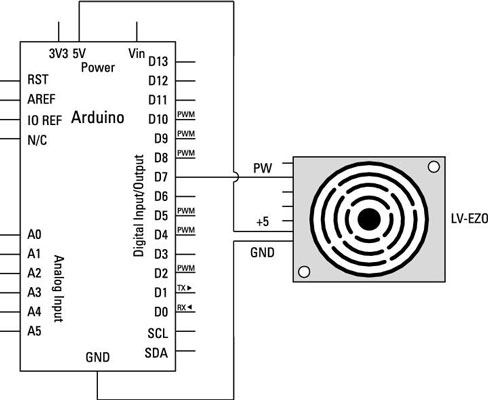
Complete the circuit from the layout and circuit diagrams. The connections for the range finder are clearly marked on the underside of the PCB. The 5V and GND connections provide power for the sensor and should be connected to the 5V and GND supplies on your Arduino.
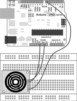
The PW connection is the pulse width signal that will be read by pin 7 on your Arduino. Make sure that your distance sensor is affixed to some sort of base pointed in the direction that you want to measure.
You can find the MaxSonar code by Bruce Allen in the Arduino playground, along with some additional notes and functions. Create a new sketch, copy or type the code into it, and save it with a memorable name, such as myMaxSonar.
//Feel free to use this code.

//Please be respectful by acknowledging the author in the code if you use or modify it.

//Author: Bruce Allen

//Date: 23/07/09


//Digital pin 7 for reading in the pulse width from the MaxSonar device.

//This variable is a constant because the pin will not change throughout execution of this code.
<b>const int</b> pwPin = 7;

//variables needed to store values
<b>long</b> pulse, inches, cm;
void setup() {
 //This opens up a serial connection to shoot the results back to the PC console
 Serial.begin(9600);
}
void loop() {
 pinMode(pwPin, INPUT);
 //Used to read in the pulse that is being sent by the MaxSonar device.
 //Pulse Width representation with a scale factor of 147 us per Inch.
 pulse = <b>pulseIn</b>(pwPin, <b>HIGH</b>);
 //147uS per inch
 inches = pulse/147;
 //change inches to centimetres
 cm = inches * 2.54;
 Serial.print(inches);
 Serial.print("in, ");
 Serial.print(cm);
 Serial.print("cm");
 Serial.println();
 <b>delay</b>(500);
}
Press the Compile button to check your code. The compiler highlights any grammatical errors, turning them red when they are discovered. If the sketch compiles correctly, click Upload to send the sketch to your board. When it is done uploading, open the serial monitor and you should see the distance measured in inches and centimeters. If the value is fluctuating, try using an object with a bigger surface.
This sketch allows you to accurately measure distance in a straight line. Test this with a tape measure and make adjustments to the code if you find discrepancies.