A first-order RC series circuit has one resistor (or network of resistors) and one capacitor connected in series. First-order RC circuits can be analyzed using first-order differential equations. By analyzing a first-order circuit, you can understand its timing and delays.
Here is an example of a first-order series RC circuit.

If your RC series circuit has a capacitor connected with a network of resistors rather than a single resistor, you can use the same approach to analyze the circuit. You just have to find the Thévenin equivalent first, reducing the resistor network to a single resistor in series with a single voltage source.
The simple RC series circuit shown here is driven by a voltage source. Because the resistor and capacitor are connected in series, they must have the same current i(t). For the sample circuit and what follows next, let R=RT.
To find the voltage across the resistor vR(t), you use Ohm’s law for a resistor device:
vR(t) = Ri(t)
The element constraint for a capacitor is given as
where v(t) is the capacitor voltage.
Generating current through a capacitor takes a changing voltage. If the capacitor voltage doesn’t change, the current in the capacitor equals 0. Zero current implies infinite resistance for constant voltage across the capacitor.
Now substitute the capacitor current i(t) = Cdv(t)/dt into Ohm’s law for resistor R, because the same current flows through the resistor and capacitor. This gives you the voltage across the resistor, vR(t):
Kirchhoff’s voltage law (KVL) says the sum of the voltage rises and drops around a loop of a circuit is equal to 0. Using KVL for the sample RC series circuit gives you
vT(t) =vR(t) +v(t)
Now substitute vR(t) into KVL:
You now have a first-order differential equation where the unknown function is the capacitor voltage. Knowing the voltage across the capacitor gives you the electrical energy stored in a capacitor.
In general, the capacitor voltage is referred to as a state variable because the capacitor voltage describes the state or behavior of the circuit at any time.
An easy way to remember that state variables — such as the capacitor voltage vC(t) and inductor current iL(t) — describe the present situation of the circuit is to think of your car’s position and instantaneous velocity as your car’s state variables. If you’re racing along the majestic road of Rocky Mountain National Park, your GPS position and car’s speed describe the current state of your driving.
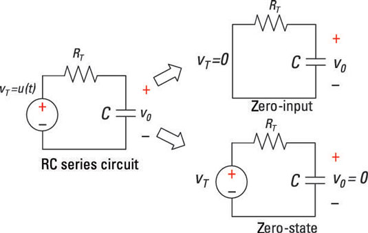
The RC series circuit is a first-order circuit because it’s described by a first-order differential equation. A circuit reduced to having a single equivalent capacitance and a single equivalent resistance is also a first-order circuit. The circuit has an applied input voltage vT(t).
To find the total response of an RC series circuit, you need to find the zero-input response and the zero-state response and then add them together. Here is an RC series circuit broken up into two circuits. The top-right diagram shows the zero-input response, which you get by setting the input to 0. The bottom-right diagram shows the zero-state response, which you get by setting the initial conditions to 0.