The only thing better than sending signals to Processing is sending multiple signals, right? Sending multiple signals is often a stumbling block, though, because although sending values from multiple sensors is easy, handling them in the correct order on the other end can often be difficult.
You need:
An Arduino Uno
A breadboard
Two 10k ohm potentiometers
A pushbutton
A 10k ohm resistor
Jump wires
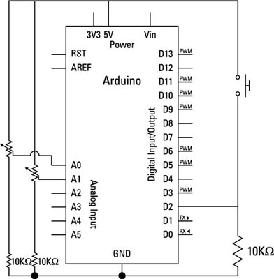
The circuit is a combination of three separate inputs. Although they all use the same power and ground, you can think of the inputs individually. Two potentiometers provide two values. These are wired in the same way you would wire a temperature sensor, with one side wired to 5V and the other wired to the analog input pin that is reading it as well as to GND via a resistor.
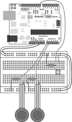
These could actually be replaced with any analog inputs with the appropriate resistors. The pushbutton provides a digital input as well. One side of the pushbutton is wired to 5V and the other is wired to the digital pin reading it as well as GND via a resistor.
How to set up the Arduino code
After you assemble your circuit, you need the appropriate software to use it. From the Arduino menu, choose File→Examples→04.Communication→SerialCallResponse. This sketch contains both Arduino code and the relevant Processing code for the sketch to work. The Processing code beneath the Arduino code is commented out to avoid interference with the Arduino sketch.
/*
 Serial Call and Response
 Language: Wiring/Arduino
 This program sends an ASCII A (byte of value 65) on startup
 and repeats that until it gets some data in.
 Then it waits for a byte in the serial port, and
 sends three sensor values whenever it gets a byte in.
 Thanks to Greg Shakar and Scott Fitzgerald for the improvements
 The circuit:
 * potentiometers attached to analog inputs 0 and 1
 * pushbutton attached to digital I/O 2
 Created 26 Sept. 2005
 by Tom Igoe
 modified 24 April 2012
 by Tom Igoe and Scott Fitzgerald
 This example code is in the public domain.
 http://www.arduino.cc/en/Tutorial/SerialCallResponse
 */
<b>int</b> firstSensor = 0; // first analog sensor
<b>int</b> secondSensor = 0; // second analog sensor
<b>int</b> thirdSensor = 0; // digital sensor
<b>int</b> inByte = 0;   // incoming serial byte
void setup()
{
 // start serial port at 9600 bps:
 Serial.begin(9600);
 while (!Serial) {
 ; // wait for serial port to connect. Needed for Leonardo only
 }
 <b>pinMode</b>(2, <b>INPUT</b>); // digital sensor is on digital pin 2
 establishContact(); // send a byte to establish contact until receiver
      // responds
}
void loop()
{
 // if we get a valid byte, read analog ins:
 if (Serial.available() > 0) {
 // get incoming byte:
 inByte = <b>Serial.read</b>();
 // read first analog input, divide by 4 to make the range 0-255:
 firstSensor = <b>analogRead</b>(A0)/4;
 // delay 10ms to let the ADC recover:
 <b>delay</b>(10);
 // read second analog input, divide by 4 to make the range 0-255:
 secondSensor = <b>analogRead</b>(1)/4;
 // read switch, map it to 0 or 255L
 thirdSensor = <b>map</b>(<b>digitalRead</b>(2), 0, 1, 0, 255);
 // send sensor values:
 <b>Serial.write</b>(firstSensor);
 <b>Serial.write</b>(secondSensor);
 <b>Serial.write</b>(thirdSensor);
 }
}
<b>void</b> establishContact() {
 while (Serial.available() <= 0) {
 <b>Serial.print</b>(<b>'A'</b>); // send a capital A
 <b>delay</b>(300);
 }
}
Upload this code to your Arduino.
How to set up the Processing code
You find the Processing code within multiline comment markers (/* */) at the bottom of the Arduino SerialCallResponse sketch. Copy the code within the comment markers into a new Processing sketch and save with an appropriate name.
// This example code is in the public domain.
<b>import</b> processing.serial.*;
<b>int</b> bgcolor;   // Background color
<b>int</b> fgcolor;   // Fill color
Serial myPort;      // The serial port
<b>int</b>[] serialInArray = <b>new int</b>[3]; // Where we'll put what we receive
<b>int</b> serialCount = 0;     // A count of how many bytes we receive
<b>int</b> xpos, ypos;     // Starting position of the ball
<b>boolean</b> firstContact = <b>false</b>;  // Whether we've heard from the
          // microcontroller
void setup() {
 <b>size</b>(256, 256); // Stage size
 <b>noStroke</b>();  // No border on the next thing drawn
 // Set the starting position of the ball (middle of the stage)
 xpos = <b>width</b>/2;
 ypos = <b>height</b>/2;
 // Print a list of the serial ports, for debugging purposes:
 <b>println</b>(Serial.<b>list</b>());
 // I know that the first port in the serial list on my mac
 // is always my FTDI adaptor, so I open Serial.list()[0].
 // On Windows machines, this generally opens COM1.
 // Open whatever port is the one you're using.
 <b>String</b> portName = Serial.<b>list</b>()[0];
 myPort = <b>new</b> Serial(<b>this</b>, portName, 9600);
}
void draw() {
 <b>background</b>(bgcolor);
 <b>fill</b>(fgcolor);
 // Draw the shape
 <b>ellipse</b>(xpos, ypos, 20, 20);
}
<b>void</b> serialEvent(Serial myPort) {
 // read a byte from the serial port:
 <b>int</b> inByte = myPort.read();
 // if this is the first byte received, and it's an A,
 // clear the serial buffer and note that you've
 // had first contact from the microcontroller.
 // Otherwise, add the incoming byte to the array:
 <b>if</b> (firstContact == <b>false</b>) {
 <b>if</b> (inByte == <b>'A'</b>) {
  myPort.clear();   // clear the serial port buffer
  firstContact = <b>true</b>;  // you've had first contact from the microcontroller
  myPort.write(<b>'A'</b>);  // ask for more
 }
 }
 else {
 // Add the latest byte from the serial port to array:
 serialInArray[serialCount] = inByte;
 serialCount++;
 // If we have 3 bytes:
 <b>if</b> (serialCount > 2 ) {
  xpos = serialInArray[0];
  ypos = serialInArray[1];
  fgcolor = serialInArray[2];
  // print the values (for debugging purposes only):
  <b>println</b>(xpos + <b>"t"</b> + ypos + <b>"t"</b> + fgcolor);
  // Send a capital A to request new sensor readings:
  myPort.write(<b>'A'</b>);
  // Reset serialCount:
  serialCount = 0;
 }
 }
}
Click the Run button to execute the Processing sketch, and an applet appears. The applet has a black background, and whenever you press the pushbutton, a white dot appears. Move the potentiometers to move the dot horizontally and vertically. When you release the pushbutton, the dot disappears.