Think of calibrating your circuit as setting the thermostat in your home. By calibrating the sensors on your Arduino project, you can tailor the sensor to its location. In this example, you learn how to calibrate a light sensor.
Light, of course, is highly variable, whether you’re inside, outside, in a well-lit room, or working by candlelight. Despite the huge variation, all these ranges of light can be sensed and interpreted by your Arduino as long as it knows the range that you’re working to. The following sketch shows you how to calibrate a light sensor to its surroundings.
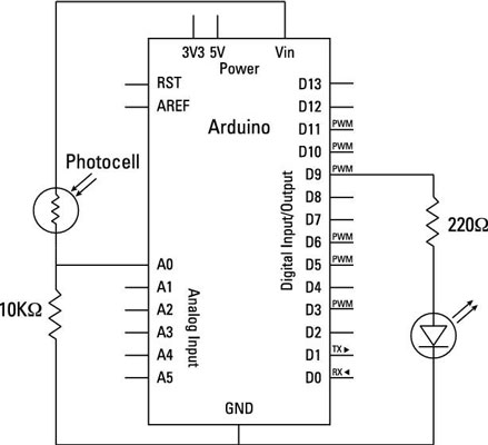
Complete the circuit to calibrate your light sensor automatically.
You need:
An Arduino Uno
A breadboard
An LED
A light sensor
A 10k ohm resistor
A 220 ohm resistor
Jump wires

Build the circuit and go to File→Examples→03.Analog→Calibration and to find the sketch. The code for this example is as follows:
/*
 Calibration
 Demonstrates one technique for calibrating sensor input. The
 sensor readings during the first five seconds of the sketch
 execution define the minimum and maximum of expected values
 attached to the sensor pin.
 The sensor minimum and maximum initial values may seem backwards.
 Initially, you set the minimum high and listen for anything
 lower, saving it as the new minimum. Likewise, you set the
 maximum low and listen for anything higher as the new maximum.
 The circuit:
 * Analog sensor (potentiometer will do) attached to analog input 0
 * LED attached from digital pin 9 to ground
 created 29 Oct 2008
 By David A Mellis
 modified 30 Aug 2011
 By Tom Igoe
 http://arduino.cc/en/Tutorial/Calibration
 This example code is in the public domain.
 */
// These constants won't change:
<b>const int</b> sensorPin = A0; // pin that the sensor is attached to
<b>const int</b> ledPin = 9;  // pin that the LED is attached to
// variables:
<b>int</b> sensorValue = 0;   // the sensor value
<b>int</b> sensorMin = 1023;  // minimum sensor value
<b>int</b> sensorMax = 0;   // maximum sensor value
void setup() {
 // turn on LED to signal the start of the calibration period:
 pinMode(13, OUTPUT);
 digitalWrite(13, HIGH);
 // calibrate during the first five seconds
 <b>while</b> (<b>millis</b>() < 5000) {
 sensorValue = <b>analogRead</b>(sensorPin);
 // record the maximum sensor value
 <b>if</b> (sensorValue > sensorMax) {
  sensorMax = sensorValue;
 }
 // record the minimum sensor value
 <b>if</b> (sensorValue < sensorMin) {
  sensorMin = sensorValue;
 }
 }
 // signal the end of the calibration period
 digitalWrite(13, LOW);
}
void loop() {
 // read the sensor:
 sensorValue = <b>analogRead</b>(sensorPin);
 // apply the calibration to the sensor reading
 sensorValue = <b>map</b>(sensorValue, sensorMin, sensorMax, 0, 255);
 // in case the sensor value is outside the range seen during calibration
 sensorValue = <b>constrain</b>(sensorValue, 0, 255);
 // fade the LED using the calibrated value:
 <b>analogWrite</b>(ledPin, sensorValue);
}
Upload the sketch, and let your Arduino settle with your normal ambient light levels for five seconds. Then try moving your hand over it. You should find it a lot more responsive than it is when it’s just reading the analog value normally, and the LED should have a range from fully on when it is open to fully off when it is covered.