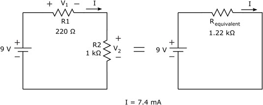
To figure out how much voltage is dropped across each resistor, you use Ohm's Law for each individual resistor. You know the value of each resistor, and you know the current flowing through each resistor. Remember that current (I) is the battery voltage (9 V) divided by the total resistance (R1 + R2), or approximately 7.4 mA.
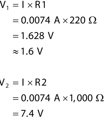
Now you can apply Ohm's Law to each resistor to calculate its voltage drop:
Note that if you add the voltage drops across the two resistors, you get 9 volts, which is the total voltage supplied by the battery. That isn't a coincidence; the battery is supplying voltage to the two resistors in the circuit, and the supply voltage is divided between the resistors proportionally, according to the values of the resistors. This type of circuit is known as a voltage divider.
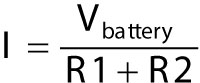
There's a quicker way to calculate either of the "divided voltages" (V1 or V2) in this figure. You know that the current passing through the circuit can be expressed as
You also know that:
and
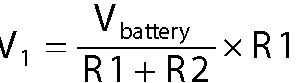
To calculate V1, for example, you can substitute the expression for I shown above, and you get
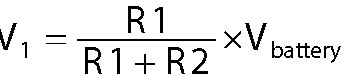
You can rearrange the terms, without changing the equation, to get
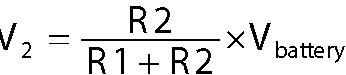
Similarly, the equation for V2 is
By plugging in the values of R1, R2, and Vbattery, you get V1 = 1.628 V and V2 = 7.4 V, just as calculated.
The following general equation is commonly used for the voltage across a resistor (R1) in a voltage divider circuit:
Many electronic systems use voltage dividers to bring down a supply voltage to a lower level, after which they feed that reduced voltage into the input of another part of the overall system that requires that lower voltage.
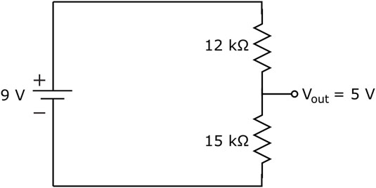
You can use the voltage divider equation to calculate the output voltage, Vout, of a voltage divider circuit, which is shown in the following figure, as follows:
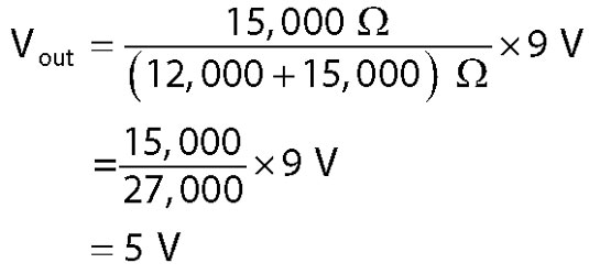
The circuit in the following figure divides a 9 V supply down to 5 V.