


With transformation, you can modify a complex circuit so that in the transformed circuit, the devices are all connected in series or in parallel. By transforming circuits, you can apply shortcuts such as the current divider technique and the voltage divider technique to analyze circuits.
Each device in a series circuit has the same current, and each device in a parallel circuit has the same voltage. Therefore, finding the current in each device in a circuit is easier when the devices are all connected in parallel, and finding the voltage is easier when they’re all connected in series.
Through a circuit transformation, or makeover, you can treat a complex circuit as though all its devices were arranged the same way — in parallel or in series — by appropriately changing the independent source to either a current or voltage source.
Changing the practical voltage source to an equivalent current source (or vice versa) requires the following conditions:
The resistors must be equal in both circuits.
The source transformation must be constrained by vS = isR.
The constraining equation, vS = isR, looks like Ohm’s law, which should help you remember what to do when transforming between independent voltage and current sources.
Convert to a parallel circuit with a current source
Transformation techniques let you convert a practical voltage source with a resistor connected in series to a current source with a resistor connected in parallel. Therefore, you can convert a relatively complex circuit to an equivalent circuit if all the devices in the external circuit are connected in parallel. You can then find the current of individual devices by applying the current divider techniques.
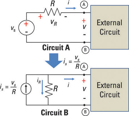
When switching from a voltage source to a current source, the resistors have to be equal in both circuits, and the source transformation must be constrained by vS = isR. Solving the constraint equation for is allows you to algebraically convert the practical voltage source into a current source:
This sample circuit shown here illustrates the conversion of a voltage source, in Circuit A, into an equivalent current source, in Circuit B. The resistors, R, are equal, and the constraint equation was applied to change the voltage source into a current source.
The sample circuit below shows the conversion with some numbers plugged in. Both circuits contain the same 3-kΩ resistor, and the source voltage in Circuit A is 15 volts. With this information, you can find the source current, is, for the transformed Circuit B.
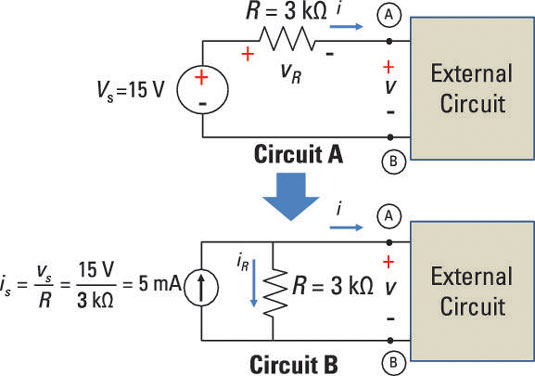
Use the constraint equation to find the source current in Circuit B. Here’s what you get when you plug in the numbers:
Convert to a series circuit with a voltage source
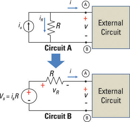
You can convert a current source connected in parallel with a resistor to a voltage source connected in series with a resistor. You use this technique to form an equivalent circuit when the external circuit has devices connected in series.
Converting a practical current source connected with a resistor in parallel to a voltage source connected with a resistor in series follows the conditions for equivalent circuits:
The resistors must be equal in both circuits.
The source transformation must be constrained by vS = isR.
This circuit illustrates how to convert a current source into a voltage source.
The sample circuit shown below depicts the same transformation of a current source to a voltage source with some numbers plugged in. Both circuits contain the same 3-kΩ resistor, and the current source in Circuit A is 5 mA.
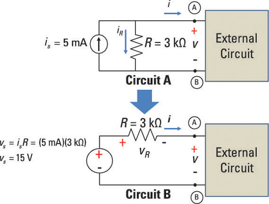
You can use the constraint equation to find the source voltage for Circuit B. Plugging in the numbers produces the following:
vs = isR = (5 mA)(3 kΩ) = 15 V
Suppose you have a complex circuit that has a current source, a resistor connected in parallel, and an external circuit with multiple resistors connected in series. You can transform the circuit so that it has a voltage source connected with all the resistors in series.
Consider Circuit A in the sample circuit below, where the right side of Terminals A and B consists of two resistors connected in series.
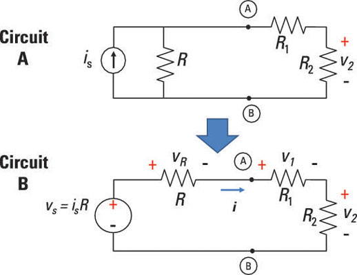
On the left side of Terminals A and B is a practical current source modeled as an ideal current source in parallel with a resistor.
You want all the devices to be connected in series, so you need to move R when you transform the circuit. To transform the circuit, change the current source to a voltage source and move R so that it’s connected in series rather than in parallel. When you use the constraint equation vs = isR to find the source voltage, remember that R is the resistor you moved.
Circuit B is a series circuit where all the devices share the same current. You can now find the voltage through R, R1, and R2 using voltage divider techniques.


