


In circuits, inductors resist instantaneous changes in current and store magnetic energy. Inductors are electromagnetic devices that find heavy use in radiofrequency (RF) circuits. They serve as RF “chokes,” blocking high-frequency signals.
This application of inductor circuits is called filtering. Electronic filters select or block whichever frequencies the user chooses.
Describe an inductor
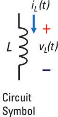
Unlike capacitors, which are electrostatic devices, inductors are electromagnetic devices. Whereas capacitors avoid an instantaneous change in voltage, inductors prevent an abrupt change in current. Inductors are wires wound into several loops to form coils. In fact, the inductor’s symbol looks like a coil of wire, as shown here.
Current flowing through a wire creates a magnetic field, and the magnetic field lines encircle the wire along its axis. The concentration, or density, of the magnetic field lines is called magnetic flux. The coiled shape of inductors increases the magnetic flux that naturally occurs when current flows through a straight wire. The greater the flux, the greater the inductance.
If you needed a circuit that stored more magnetic energy, you could get even larger inductance values by inserting iron into the wire coil.
Here’s the defining equation for the inductor:
where the inductance L is a constant measured in henries (H). Here is the same equation in graphical form.
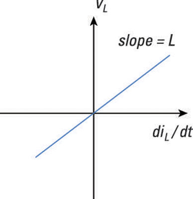
The figure shows the i-v characteristic of an inductor, where the slope of the line is the value of the inductance.
The preceding equation says that the voltage across the inductor depends on the time rate of change of the current. In other words, no change in inductor current means no voltage across the inductor. To create voltage across the inductor, current must change smoothly. Otherwise, an instantaneous change in current would create one humongous voltage across the inductor.
Think of inductance L as a proportionality constant, like a resistor acts as a constant in Ohm’s law. This notion of Ohm’s law for inductors (and capacitors) becomes useful when you start working with phasors.
To express the current through the inductor in terms of the voltage, you integrate the preceding equation as follows:
The second term in this equation is the initial current through the inductor at time t = 0.
Find the energy storage of an attractive inductor
To find the energy stored in the inductor, you need the following power definition, which applies to any device:
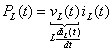
The subscript L denotes an inductor device. Substituting the voltage for an inductor into the power equation gives you the following:
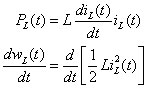
The energy wL(t) stored per unit time is the power. Integrating the preceding equation gives you the energy stored in an inductor:
The energy equation implies that the energy in the inductor is always positive. The inductor absorbs power from a circuit when storing energy, and the inductor releases the stored energy when delivering energy to the circuit.
To visualize the current and energy relationship shown here, which shows the current as a function of time and the energy stored in an inductor.
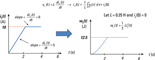
This also shows how you can get the current from the inductor relationship between current and voltage.
Calculate total inductance for series and parallel inductors
Inductors connected in series or connected in parallel can be reduced to one single inductor. Take a look at the circuit with three series inductors shown in the top diagram.
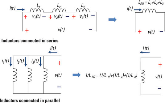
Because the inductors are connected in series, they have the same currents:
i1(t) = i2(t) =i3(t) = i(t)
Add up the voltages from the series inductors to get the net voltage v(t), as follows:
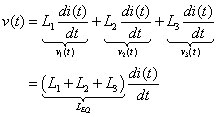
For a series inductors, you have an equivalent inductance of
LEQ = L1 + L2 + L3
For a parallel connection of inductors, apply Kirchhoff’s current law (KCL) in the bottom diagram of the figure. KCL says the sum of the incoming currents and outgoing current at a node is equal to 0, giving you
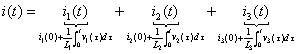
Because you have the same voltage v(t) across each of the parallel inductors, you can rewrite the equation as
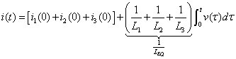
This equation shows how you can reduce the parallel inductors to one single inductor:


