
A Thévenin or Norton equivalent circuit is valuable for analyzing the source and load parts of a circuit. Thévenin’s and Norton’s theorem allow you to replace a complicated array of independent sources and resistors, turning the source circuit into a single independent source connected with a single resistor.
Using the Thévenin or Norton equivalent of a circuit allows you to avoid having to reanalyze the entire circuit over and over again, just to try out different loads.
Apply Thévenin’s theorem to circuit analysis
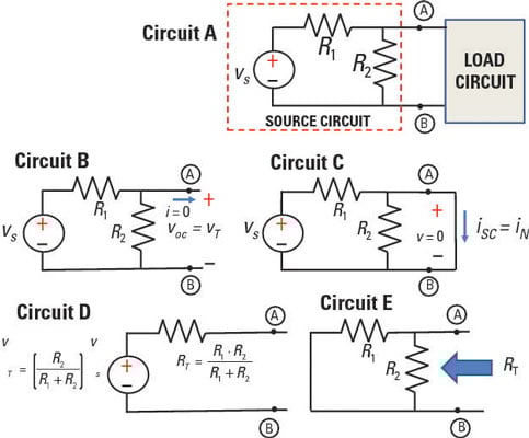
To simplify your analysis when interfacing between source and load circuits, the Thévenin method replaces a complex source circuit with a single voltage source in series with a single resistor. To obtain the Thévenin equivalent, you need to calculate the open-circuit voltage voc and the short-circuit current isc.
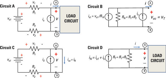
Circuit A shown here is a source circuit with an independent voltage source connected to a load circuit. Circuit B shows the same circuit, except that the load circuit has been replaced with an open-circuit load. You use the open-circuit load to get the Thévenin voltage, vT, across Terminals A and B. The Thévenin voltage equals the open-circuit voltage, voc.
The voltage is driven by a voltage source for this series circuit, so use the voltage divider technique to get voc:
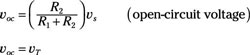
Solving for voc gives you the Thévenin voltage, vT.
Circuit C shows the same source circuit as a short-circuit load. You use the short-circuit load to get the Norton current, iN, through Terminals A and B. And you find the Norton current by finding the short-circuit current, isc.
In Circuit C, the short circuit is in parallel with resistor R2. This means that all the current coming out from resistor R1 will flow through the short because the short has zero resistance. In other words, the short bypasses R2. You can find the current through Terminals A and B using Ohm’s law, producing the short-circuit current:
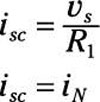
This short-circuit current, isc, gives you the Norton current, iN.
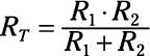
Finally, to get the Thévenin resistance, RT, you divide the open-circuit voltage by the short-circuit current. You then wind up with the following expression for RT:
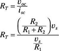
Simplify that equation to get the Thévenin resistance:
Circuit D shows the Thévenin equivalent for the source circuit in Circuit A.
The preceding equation looks like the total resistance for the parallel connection between resistors R1 and R2 when you short (or remove) the voltage source and look back from Terminals A and B.
When looking to the left from the Terminals A and B, you can find the Thévenin resistance RT by removing all independent sources by shorting voltage sources and replacing current sources with open circuits. After getting rid of the independent sources, you can find the total resistance between Terminals A and B, shown in Circuit E of the sample circuit. (Note that this tactic only works when there are no dependent sources.)
Apply Norton’s theorem to circuit analysis
To see how to use the Norton approach for circuits with multiple sources, consider Circuit A in the sample circuit shown here.

Because it doesn’t matter whether you find the short-circuit current or the open-circuit voltage first, you can begin by determining the open-circuit voltage. Putting an open load at Terminals A and B results in Circuit B. The following analysis shows you how to obtain is1 and RN in Circuit B.
Applying Kirchhoff’s voltage law (KVL) in Circuit A lets you determine the open-circuit voltage, voc. KVL says that the sum of the voltage rises and drops around the loop is zero. Assuming an open circuit load for Circuit A, you get the following KVL equation (where the load is an open circuit, v = voc):
Algebraically solve for voc to get the open-circuit voltage:
The current supplied by the voltage source vs goes through resistors R1 and R2 because the current going through an open circuit load is zero. In Circuit B, you can view the current source is as a device having an infinite resistance (that is, as an open circuit).
However, all the current provided by the current source is will go through R1 and R2, and none of the current from is will go through the open-circuit load. Applying Ohm’s law (v = iR), you have the following voltages across resistors R1 and R2:
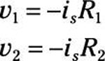
The minus sign appears in these equations because the current from is flows opposite in direction to the assigned voltage polarities across the resistors.
Substitute v1 and v2 into the expression for voc, and you wind up with the following open-circuit voltage:
The open-circuit voltage is equal to the Thévenin equivalent voltage, voc = vT.
Next, find the short-circuit current in Circuit C of sample circuit shown here.
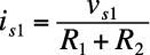
The current is1 supplied by the voltage source will flow only through resistors R1 and R2, not through the current source is, which has infinite resistance. Because of the short circuit, the resistors R1 and R2 are connected in series, resulting in an equivalent resistance of R1 + R2. Applying Ohm’s law to this series combination gives you the following expression for is1 provided by the voltage source vs1:
Kirchhoff’s current law (KCL) says that the sum of the incoming currents is equal to the sum of the outgoing currents at a node. Applying KCL at Node A, you get
Substituting the expression for is1 into the preceding KCL equation gives you the short-circuit current, isc:
The Norton current iN is equal to the short-circuit current: iN = isc.
Finally, divide the open-circuit voltage by the short-circuit current to get the Norton resistance, RN:
Plugging in the expressions for voc and isc gives you the Norton resistance:
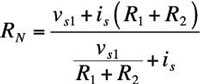
Adding the terms in the denominator requires adding fractions, so rewrite the terms so they have a common denominator. Algebraically, the equation simplifies as follows:
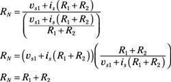
When you look left from the right of Terminals A and B, the Norton resistance is equal to the total resistance while removing all the independent sources. You see the Norton equivalent in Circuit D of the sample circuit, where RT = RN.