


Filter circuits (such as low-pass filters, high-pass filters, band-pass filters, and band-reject filters) shape the frequency content of signals by allowing only certain frequencies to pass through. You can describe these filters based on simple circuits.
You find the sinusoidal steady-state output of the filter by evaluating the transfer function T(s) at s = jω. The transfer function relates the input/output signals in the s-domain and assumes zero initial conditions. The radian frequency ω is a variable that stands for the frequency of the sinusoidal input. After you substitute the s = jω into T(s), the transfer function becomes a ratio of complex numbers T(jω).
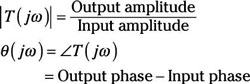
Because the function T(jω) is a complex number for all frequencies, you can determine the gain |T(jω)| and phase θ(jω). Here are the gain and phase relationships:
You can present the gain and phase as a function of frequency ω graphically, as shown in this approximation of a typical filter. In a passband region, the gain function has nearly constant gain for a range of frequencies. In the stopband region, the gain is significantly reduced for a range of frequencies.
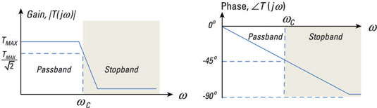
For nonideal filters, a transition region occurs between adjacent passband and stopband regions. The cutoff frequency ωC occurs within the transition region, according to a prescribed definition. One widely used definition says the cutoff frequency occurs when the passband gain is decreased by a factor of 0.707 from a maximum value TMAX. The mathematical condition for ωC is therefore
At the cutoff frequency, the output power has dropped to one half of its maximum passband value. Here, the passband includes those frequencies where the relative power is greater than the half-power point (0.707 of the maximum value of the transfer function). Frequencies that are less than the half-power point fall in the stopband.
Low-pass filter
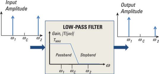
The low-pass filter has a gain response with a frequency range from zero frequency (DC) to ωC. Any input that has a frequency below the cutoff frequency ωC gets a pass, and anything above it gets attenuated or rejected. The gain approaches zero as frequency increases to infinity.
The input signal of the filter shown here has equal amplitudes at frequencies ω1 and ω2. After passing through the low-pass filter, the output amplitude at ω1 is unaffected because it's below the cutoff frequency ωC. However, at ω2, the signal amplitude is significantly decreased because it's above ωC.
High-pass filter
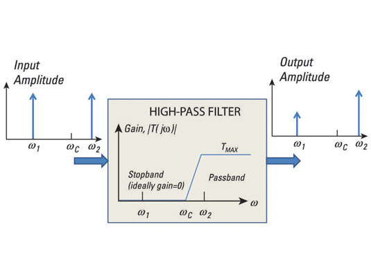
The high-pass filter has a gain response with a frequency range from ωC to infinity. Any input having a frequency below the cutoff frequency ωC gets attenuated or rejected. Anything above ωC passes through unaffected.
The input signal of the filter shown here has equal amplitude at frequencies ω1 and ω2. After passing through the high-pass filter, the output amplitude at ω1 is significantly decreased because it's below ωC, and at ω2, the signal amplitude passes through unaffected because it's above ωC.
Band-pass filters
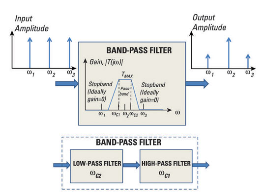
The band-pass filter has a gain response with a frequency range from ωC1 to ωC2. Any input that has frequencies between ωC1 and ωC2 gets a pass, and anything outside this range gets attenuated or rejected.
The input signal of the filter shown here has equal amplitude at frequencies ω1, ω2, and ω3. After passing through the band-pass filter, the output amplitudes at ω1 and ω3 are significantly decreased because they fall outside the desired frequency range, while the frequency at ω2 is within the desired range, so its signal amplitude passes through unaffected.
You can think of the band-pass filter as a series or cascaded connection of a low-pass filter with frequency ωC2 and a high-pass filter with frequency ωC1. The cascade connection of a low-pass filter and high-pass filter forms a band-pass filter; the order of the filters doesn't matter.
If you're going to do a quick-and-dirty design of a band-pass filter based on a low-pass filter and high-pass filter, make sure you select the right cutoff frequencies. For example, if you give the low-pass filter a lower cutoff frequency of ωC1 and the high-pass filter an upper cutoff frequency of ωC2, you'll get a very small signal at the output, or a no-pass filter — everything gets rejected.
Band-reject (bandstop) filters
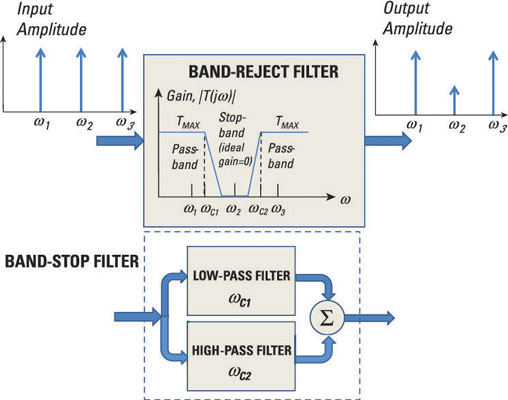
The band-reject filter, or bandstop filter, has a gain response with a frequency range from zero to ωC1 and from ωC2 to infinity. Any input that has frequencies between ωC1 and ωC2 gets significantly attenuated, and anything outside this range gets a pass.
The input signal of the filter shown here has equal amplitude at frequencies ω1, ω2, and ω3. After passing through the band-reject filter, the output amplitude at ω1 and ω3 is unaffected because those frequencies fall outside the range of ωC1 to ωC2. But at ω2, the signal amplitude gets attenuated because it falls within this range.
You can think of the band-pass filter as a parallel connection of a low-pass filter with cutoff frequency ωC1 and a high-pass filter with cutoff frequency ωC2.with their outputs added together. The bottom diagram shows the parallel connection of a low-pass filter and high-pass filter to form a band-reject filter.
Make sure you select the right cutoff frequencies when you do a quick-and-dirty design of a band-reject filter based on a low-pass filter and high-pass filter connected in parallel. Shown here, if you give the low-pass filter a lower cutoff frequency of ωC2 and the high-pass filter an upper cutoff frequency of ωC1, you'll have signals of all frequencies passing through the filter — not good for a band-reject filter.
What you'll design instead is an all-pass filter. It's like using a coffee filter with a big, fat hole in it — everything passes through, including the coffee grounds.


