Arduino For Dummies Cheat Sheet

This cheat sheet contains nuggets of information about using resistors, gathering the tools you'll need, and system shortcuts to help you on your way to becoming an Arduino aficionado.
How to use pinout diagrams for reference
Pinout diagrams are visual maps of an Arduino board that show what each pin does and how it is connected internally. They are an essential reference when wiring components, choosing pins for specific functions, or checking electrical limits.
A pinout diagram typically shows:
- Digital pins and which support special features such as PWM
- Analog input pins
- Power pins (5V, 3.3V, GND, VIN)
- Communication pins for I2C, SPI, and serial (UART)
- Built-in components, such as LEDs or onboard regulators
- Maximum current limits for individual pins and for the board as a whole
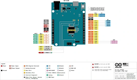
For example, the Arduino Uno R4 Minima pinout clearly shows that:
- Each I/O pin has a maximum current of 8 mA
- The maximum total current across all pins is 60 mA
- Some pins share functions (for example, analog pins A4 and A5 are also used for I2C)
- SPI pins may be labeled using the newer CIPO/COPI terminology (previously known as MISO/MOSI)
The following image shows a pinout diagram for the Arduino Uno R4 Minima, showing power, I/O, and communication pins.
Where to find pinout diagrams
The most reliable source for pinout diagrams is the official Arduino documentation:
- Go to docs.arduino.cc
- Navigate to the page for your specific board
- Look for the “Pinout” or “Resources” section
Arduino provides high-quality, downloadable pinout diagrams for all current boards, including the Uno R4 Minima. These diagrams are kept up to date and are ideal for printing or keeping open while you work.
When to check a pinout diagram
Refer to the pinout diagram when you:
- Are unsure which pins support PWM, I2C, SPI, or serial
- Need to confirm power and ground connections
- Want to avoid exceeding current limits
- Are using a new or unfamiliar Arduino board
Keeping the pinout diagram nearby can save time and help prevent wiring mistakes that could damage your board.
Using resistors in Arduino
When building your Arduino projects, you use resistors to limit the amount of current going to certain components in the circuit, such as LEDs and integrated circuits. To calculate the resistance, you should use a modified version of Ohm’s Law.
In the following equation, R is resistance; VSUPPLY is the voltage supplied from the power source (this is 5V for a standard Arduino digital pin, but could be more or less if the VIN pin is used); VFORWARD is the voltage required by the component, and I is the current required by the component:
R = (VSUPPLY – VFORWARD) / I
Here is an example for powering an LED:
(5V – 2V) / 0.02A = 150Ω
In practice, you often choose the next standard resistor value up to be safe.
After you’ve determined which resistor you need, the next task is to find it. Fixed-value resistors use colored bands to indicate the value of the resistor. Most beginner kits use 4-band resistors; 5-band resistors are read slightly differently. To find the value you can use a multimeter on the ohms (Ω) setting, but if you don’t have a multimeter handy, use the following table to find the value instead. For example, a resistor with brown, black, brown, and gold bands is a 100Ω resistor with a 5% tolerance.
In addition, the Circuit Playground by Adafruit has resistor color codes as well as a variety of other useful tools for building circuits.
Resistor color chart
How to get the right tools for your Arduino project
When you start to build your Arduino project, it’s hard to know what tools and equipment to buy. Following is the recommended equipment for solder-less prototyping, which is a good way to start. Next is a list of equipment for soldering, which help you to toughen up your prototype for the real world. Note: Consider buying tools as you need them. You never know what you’ll need next, and tools can get expensive.
What you need for solder-less prototyping
- Breadboard: This allows you to prototype a circuit without permanently fixing anything in place.
- Jump wires: These are tiny lengths of wire that are ideal for building circuits on a breadboard.
- Needle-nosed pliers: These have a pointed nose to allow you to hold tiny objects with great precision. They’ll save you a lot of swearing!
- Multimeter: A good meter can measure volts, amps, resistance and continuity amongst other things.
- Power supply: Similar to the power supplies for laptops. A 12V DC power supply with a 2.1mm jack is good for many small applications — just make sure that it supplies enough current!
For many beginner projects, powering the board via USB is the simplest and safest option.
What you need for soldering
- Soldering iron: Comes as fixed-temperature, temperature-controlled, gas-powered, or a solder station. Getting a temperature-controlled iron will set you back about $30 (£20) and is a good investment until you can justify getting a nice solder station, such as those made by Weller.
- Solder: Buying lead-free solder is a good idea for your health and the environment.
- Third hand: Also known as a helping hand, this tool is good for holding boards and components in place.
- Adhesive putty: Cheaper than a helping hand and often more reliable for arranging your circuit and components for soldering.
- Wire cutters: A good set of wire cutters will have a pointed nose for precision clipping.
- Wire strippers: Can be manual or mechanical. If you can, try them out in a shop to find your preference for the wire you are intending to strip.
- Solder sucker: This is a vacuum tube that’s useful for undoing soldering mistakes.
- Solder wick: Another way to undo mistakes is to melt excess solder into a piece of solder wick.
- Equipment wire: Buying a few short reels or multicore equipment wire in various colors is always a good idea.
- This equipment is most easily available from online retailers such as Adafruit and Sparkfun, as well as their worldwide distributors.
Taking a shortcut when coding your project
After you have built your Arduino project, you may have many hours ahead of tweaking the code until it’s perfect. It’s handy to know a few shortcuts to speed up the process. Here are the some of the most useful:
These shortcuts apply to the current Arduino IDE at the time of writing; some behavior may vary slightly in newer versions.
About This Article
This article can be found in the category:
Hot off the press
Explore Related content