


 An AutoCAD drawing, in less than five minutes!
Follow these steps to produce a 2D view from a 3D model:
- Click the Workspace Switching button on the status bar, and then choose 3D Modeling.
Toolbars, palettes, and Ribbon panels flash on and off, and soon AutoCAD settles down to display the Ribbon, as configured for the 3D Modeling workspace with a few additional panels. - Set up a 3D model.
Create a new model or open an existing file that contains a 3D model.You can find the files used here at this link. Go to and download afd23.zip. The drawing named afd23a.dwg contains the model Use in the following steps. - Switch to paper space.
Click the Layout 1 tab near the lower-left corner of the screen. - Delete the existing viewport by clicking the viewport object (the frame of the viewport) and then pressing Delete.
By default, new drawings created from a standard template file contain a single viewport. If you’ll frequently create new drawings like this, set up a template file with the viewport already deleted. - Click the Base button from the Create View panel on the Layout tab of the Ribbon, and then choose From Model Space from the drop-down list.
The VIEWBASE command creates several new layers automatically. By default, they’re the opposite of the screen color (black or white), but they always print in black. You can change these layers to any color you want. - Position the base view.
AutoCAD automatically selects what it thinks is an appropriate scale, assuming that you’ll place the three standard orthographic views and one pictorial view. However, you can change it. Select a suitable place in the lower-left quadrant of the layout sheet.The Drawing View Creation contextual tab appears on the Ribbon, a drop-down list of view options appears at the cursor, and an option list appears on the command line. The Drawing View Creation context tab of the Ribbon.
 - Define the base view.
Using any one of the three selection methods — Ribbon, cursor, or command line — set up the base view as follows:- Orientation: The view shows what appears to be the bottom view of the part because AutoCAD defines top, bottom, and so on relative to the world X,Y coordinates. Select Orientation and the Top to create the view you want.
- Hidden lines: The preview image in paper space always displays in shaded mode, regardless of the visual style of the model in model space. Change the Hidden Lines option to Visible and Hidden. The view won’t change yet, but don’t worry — it will after you complete the steps.
- Scale: This setting defaults to 1:4, which is suitable for your purposes if you started from the sample drawing.
- Visibility, or Edge Visibility: This setting specifies how to display edges that are formed where tangent surfaces meet. The normal practice is not to display them, but it sometimes causes features to disappear (or partially disappear). If you change this setting, hover the cursor over the Edge Visibility button in the Appearance panel of the Ribbon and pause for a few seconds; a much more extensive tooltip list then explains each option.
- Move: Specify a new location for the view before it is finally created. This isn’t such a big deal, though, because views can always be easily moved later.
- Exit: Or press Enter.
You can edit any of these view specifications later, view by view.
- Place the other drawing views.
When you finish placing and defining the base view, AutoCAD automatically runs the VIEWPROJ command. All you need is three quick clicks to place the top, isometric, and right-side views; then press Enter to have AutoCAD generate the views. - Edit the isometric projection.
Isometric projections don’t normally show hidden lines. Double-click anywhere in the isometric projection to bring up the Drawing View Editor tab on the Ribbon. The Drawing View Editor context tab on the Ribbon.
Click Hidden Lines on the Appearance tab and choose Shaded with Visible Lines from the drop-down list.
If a Ribbon button has a drop-down list, the Ribbon displays the last button that was used. Any one of four different buttons may be in this particular location.
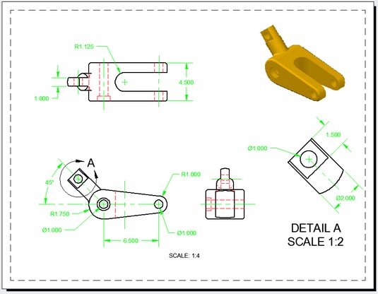
The image below shows three ortho views and a shaded isomeric view, which was created in 37.6 seconds. Average creation time: 9.4 seconds per view.
 - Add annotations.
Add dimensions and text notes in the paper space layout. Dimensions are associative to their matching geometry if you use object snaps to the geometry when you place them. While you’re at it, perhaps you can use VIEWDETAIL to create a detail view at a different scale.When you submit a drawing to your boss, they’ll be impressed that you managed to create such a complex drawing, including the shaded isometric projection, in only three days.
Place text and dimensions on their own layers.
An isometric view and an isometric projection are different creatures. An isometric view is normally drawn so that lines that are parallel to the three principal axes appear in their true length, and an isometric projection foreshortens them due to the tilting and rotating of the viewing angle of the object. Traditional paper-and-pencil drawings use isometric views, whereas AutoCAD creates isometric projections.
If you truly want an isometric view, the solution is simply to ignore the usual rule about drawing and inserting at full size. When creating an isometric projection, use this approximate scale factor to produce an isometric view:1.2247441227836356744839797834917
You can also edit the insertion later, to make it match this scale factor.
Editing views in AutoCAD
You can apply two different types of editing to 2D views that were generated from 3D models.You can edit the view specifications themselves (start with the easy one):
- Select the base view, and then select the blue grip box that appears in the center of the view.
- Drag and drop the view into a new location.
Interesting! If you move the base view, all the ortho views projected from it follow along, with some constraints. The ortho views don’t move in perfect unison as a single group, but they maintain their orthographic relationship to the base view.Similarly, you can move projected ortho views in only the direction that still maintains their ortho relationship to the base view. Better yet, all attached dimensions (you hope) also follow along.
To experience the magic of creating 2D views from a 3D model, return to model space and edit the model. For example, add a second hole (hint: subtract a cylinder), extend the length of the peg, and then return to the paper space layout. All your views and their dimensions are updated.
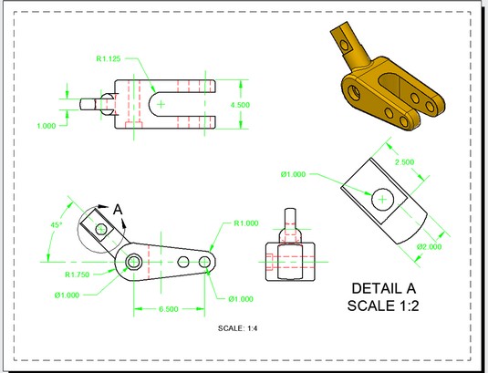 If anything changes, everything changes.
AutoCAD creates the views as a series of anonymous blocks. They behave much like regular blocks, but because they don’t have normal names, you can’t access them directly to edit or explode them
Additional 3D AutoCAD tricks
To fully cover the 3D capabilities of AutoCAD would easily require a full book on its own, but meanwhile, here are a few high points:- Don’t want four views? If you don’t want four standard views, you can create only the base view and then change its scale factor to better suit the sheet size.
- Need additional base views? If necessary, you can have more than one base view in a single layout. For example, one large drawing might show an assembly and its component parts.
- Didn’t create enough views? Use the VIEWPROJ command to add more projected views later. They don’t have to project from the original base view, but can project from an existing projected view.
- No longer need a view? You can delete a view, even a base view, without affecting the other views — except that doing so breaks the horizontal and vertical links between the views that were projected from it.
- No 3D model in your drawing? You can use the VIEWBASE command to generate views from a 3D model that lived in the model space of the current drawing.
AutoCAD’s top model
You may have generated 2D drawing views from a 3D model in model above. But if the VIEWBASE command cannot find a 3D model in the current drawing file, it opens a standard file dialog box so that you can browse for an Autodesk InventorInventor is the 3D parametric modeling software from Autodesk, primarily intended for the mechanical design field. Inventor is fully parametric, in that dimensional constraints drive the profiles that define the solid features that consist of the parts that comprise the assembly model that drives the 2D drawing views that Jack built. If you change a dimension on a 2D drawing of a part, everything updates, all the way down the line.
The Inventor file isn’t inserted into the AutoCAD file. Instead, it’s attached like an xref. VIEWBASE creates a 2D drawing view based on it, and additional views can be projected from the base view.Here’s the magic part: The AutoCAD drawing views are still linked back to the Inventor file so that any changes made to the Inventor file reflect down to the AutoCAD file, updating it.
Better yet, you can send the AutoCAD DWG file to a client or vendor without having to send the source Inventor file. The AutoCAD file contains only anonymous blocks for the 2D views and has nothing in model space.
On the other hand, whenever the AutoCAD DWG file has access to the Inventor file, the AutoCAD drawing views update and remain in step with any changes made to the Inventor model.
Here are more tips for working with AutoCAD and Inventor files:
- Mix and match 2D drawing views. If VIEWBASE finds an AutoCAD solid in your part, you can tell it to ignore it and let you attach it to an Inventor file instead. You can have more than one base view in an AutoCAD drawing, so you can mix and match 2D drawing views. One or more base views can come from an internal AutoCAD 3D model, and others can be linked to external Inventor files.
- Select additional solids. If model space contains more than one solid, VIEWBASE allows you to switch back to model space, where you can select and deselect solids to appear in the base view. For example, a model of a gearbox assembly might consist of many components. Separate views can be created, perhaps on several different layouts: one showing an outside view of the entire gearbox (which doesn’t need to include the internals such as gears and bearings); another showing only the input shaft, gear, bearings, and seals; and another showing the output shaft and its related components.
- Choose a different scale. The VIEWDETAIL command generates detail views at scales different from the parent view.
- Use different section views. The VIEWSECTION command has five options for creating section views: Full, Half, Offset, Aligned, and From Object. This command creates section views based on existing views in the layout. The cutting plane line that it generates can be manipulated like any regular polyline, and the section view then updates accordingly.


