In the field of electronics, a gated latch is a latch that has a third input that must be active in order for the SET and RESET inputs to take effect. This third input is sometimes called ENABLE because it enables the operation of the SET and RESET inputs.
The ENABLE input can be connected to a simple switch. Then, when the switch is closed, the SET and RESET inputs are enabled; when the switch is open, any changes in the SET and RESET inputs are ignored.
Alternatively, the ENABLE input can be connected to a clock pulse. For example, you could connect the output of a 555 timer circuit to the ENABLE input. Then, the latch inputs will be operational only when the 555 timer’s output is HIGH. Note that the ENABLE input is often called the CLOCK input.
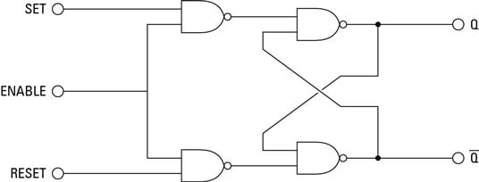
You can easily add an ENABLE input to a latch by adding a pair of NAND gates. Here, the SET and RESET inputs (SR latch) are connected to one input of each of the two NAND gates. The ENABLE input is connected to the other input of each NAND gate. Then, the output from these gates are used as the inputs to the basic latch circuit.
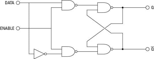
Another common type of gated latch is called a gated D latch, which has just two inputs: DATA and ENABLE. When a HIGH is received at the ENABLE input, the DATA input is copied to the output. Even if the ENABLE input then goes low, the output remains unchanged. The output cannot be changed until the ENABLE input goes high.
To create a gated D latch from a gated SR latch, you simply connect the SET and RESET inputs together through an inverter. Thus, the SET and RESET inputs will always be opposite of one another. When the DATA input is HIGH, the SET input is HIGH and the RESET input is LOW. When the DATA input is LOW, the SET input is LOW and the RESET input is HIGH.