
After finding the zero-input response and the zero-state response of an RC series circuit, you can easily find the total response of the circuit. Remember that a first-order RC series circuit has one resistor (or network of resistors) and one capacitor connected in series.
Here is a sample RC circuit shown with zero-input response and zero-state response. The top-right diagram shows the zero-input response, which you get by setting the input to 0. The bottom-right diagram shows the zero-state response, which you get by setting the initial conditions to 0.
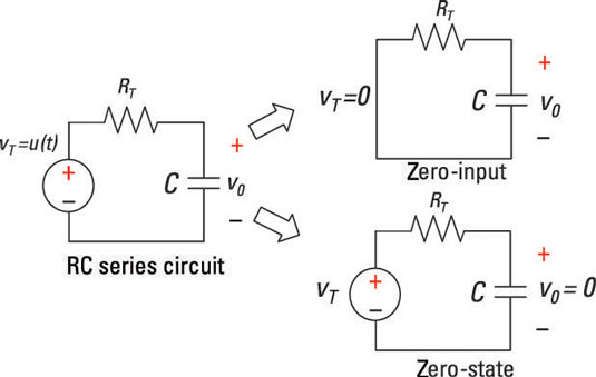
The first-order differential equation you need to find the zero-input response vZI(t) for this circuit.
After applying your math skills, you find the zero-input response of the circuit:
Now to find the zero-state response, you need to study the circuit under zero initial conditions (when there’s no voltage across the capacitor at time t = 0). The sample circuit has zero initial conditions and an input voltage of VT(t) = u(t), where u(t) is a unit step input.
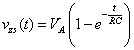
After applying your math skills again, you find the zero-state response of the circuit:
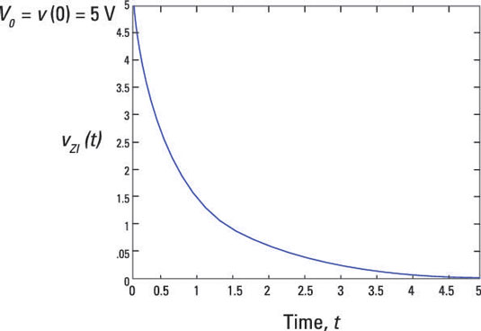
Suppose that RC = 1 second and initial voltage V0 = 5 volts. Then this chart plots the decaying exponential, showing that it takes about 5 time constants, or 5 seconds, for the capacitor voltage to decay to 0.
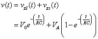
Now you are ready to finally add up the zero-input response vZI(t) and the zero-state response vZS(t) to get the total response v(t):
Time to verify whether the solution is reasonable. When t = 0, the initial voltage across the capacitor is
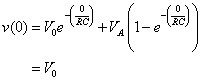
You bet this is a true statement! But you can check out when the initial conditions die out after a long period of time if you feel unsure about your solution. The output should just be related to the input voltage or step voltage.
After a long period of time (or after 5 time constants), you get the following:
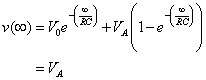
Another true statement. The output voltage follows the step input with strength VA after a long time. In other words, the capacitor voltage charges to a value equal to the strength VA of the step input after the initial condition dies out in about 5 time constants.
Try this example with these values: V0 = 5 volts, VA = 10 volts, and RC = 1 second. You should get the capacitor voltage charging from an initial voltage of 5 volts and a final voltage of 10 volts after 5 seconds (5 time constants). Using the given values, you get the plot shown here.
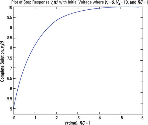
The plot starts at 5 volts, and you end up at 10 volts after 5 time constants (5 seconds = 5RC). So this example shows how changing voltage states takes time. Circuits with capacitors don’t change voltages instantaneously. A large resistor also slows things down. That’s why the time constant RC takes into account how the capacitor voltage will change from one voltage state to another.
The total capacitor voltage consists of the zero-input response and a zero-state response:
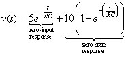
This equation shows that the total response is a combination of two outputs added together: one output due only to the initial voltage V0 = 5 volts (at time t = 0) and the other due only to the step input with strength VA = 10 volts (after time t = 0).