
- Soldering iron, preferably with both 20 and 40 W settings
- Solder
Use thicker solder for the line-voltage wires and thin solder for assembling the MK110 kit.
- Magnifying goggles
- Phillips screwdriver
- Small flat-edge jewelers screwdriver
- Wire cutters
- Wire strippers
- Pliers
- Hobby vise
- Drill with 1/8-inch, 5/32-inch, 1/4-inch, 5/16-inch, 3/8-inch, and 3/4-inch bits
- Assemble the Velleman MK110 kit.
The kit comes with simple but accurate instructions. Basically, you just mount and solder all the components onto the circuit board. Pay special attention to the color codes for the resistors and the orientation of the diode.
The assembled Velleman MK110 kit.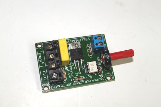
It's best to mount the circuit board in a good hobby vise and use an alligator clip or masking tape to hold the components in place while soldering.
- Drill all the mounting holes in the project box except the hole for the sensitivity control on the left side of the box.
The figure shows the orientation of the approximate location of the mounting holes.
Drill the holes as indicated in this diagram.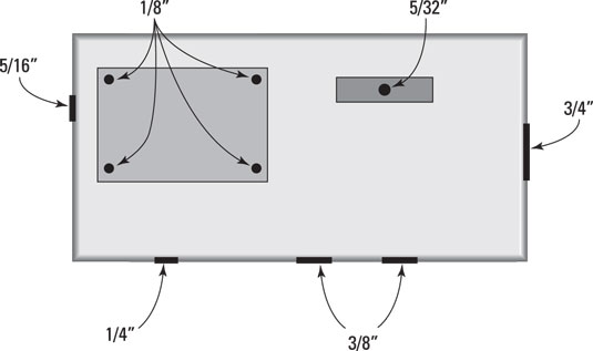
Use the assembled circuit board to determine the exact drilling locations for the four holes that will mount the circuit board. The position of the other holes isn't critical, with the exception of the hole for the potentiometer knob. Don't drill that hole until Step 4.
- Mount the four standoffs in the four MK110 circuit board mounting holes.
Use four of the machine screws that came with the standoffs.
- Drill the hole for the circuit board's potentiometer. Set the circuit board on top of the four standoffs to determine the exact location for this hole.
- Insert the two rubber grommets into the two 3/8-inch holes. The grommets are difficult to squeeze into the hole, but work at it and you'll get them in. If necessary, use the small edge of a flat screwdriver to push the rubber edges into the holes.
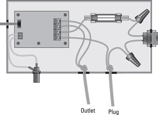
In the steps that follow, you assemble all the parts into a box. Use the following figure as a guide for the proper placement of each of the parts.
- Cut the extension cord.
First cut the outlet end of the extension cord, leaving about 12 inches of wire attached to the outlet. Then cut the plug end, leaving about 3 or 4 feet of wire attached to the plug. You'll have a few feet of wire left over; set this wire aside for later.
- Push the power cords through the grommets and tie a knot inside the box.
It will be a tight squeeze, but the cords will fit. Pull about a foot of the cord with the plug attached through the hole nearest the switch. Then, tie it in a knot, cinch the knot down tight, and pull the plug so that the knot is snug against the grommet. The knot acts as a strain relief.
Repeat the same process with the cord that's attached to the outlet, passing it through the other grommet, tying a tight knot, and pulling the knot up against the grommet.
When both power cords are in place, separate the two wires of each cord inside the project box and strip about 3/8 inch of insulation from each wire.
- Cut two 1-1/2-inch lengths of extension cord wire and solder them to the switch terminals. You'll need to strip about 3/8 inch of insulation from each end of both wires. Put your soldering iron on its High setting and use thick solder. Set the switch aside when the solder sets.
- Cut two 1-1/2-inch lengths of extension cord wire and solder them to the terminals on the fuse holder. Again, you'll need to strip about 3/8 inch of insulation from each end of both wires and solder with high heat.
- Cut two 2-1/2-inch lengths of the hookup wire and strip 3/8 inch of insulation from the ends.
- Solder one of the hookup wires to the center terminal of the RCA-style phono jack and the other wire to the ground terminal. At this point, you're done with the soldering iron, so you can turn it off.
- Mount the RCA-style phono jack in the 1/4-inch hole in the project box. To mount the jack, you'll first have to remove the nut, the ground terminal, and the lock washer from the jack. Then, pass the wire connected to the center terminal of the phono jack through the 1/4-inch hole, and then insert the threaded end of the phono jack into the hole. Slip the lock washer, the ground terminal, and the nut over the wire connected to the center terminal, and then thread them onto the threaded part of the jack. Tighten with needle-nose pliers.
In the next few steps, you attach wires to the MK110 circuit card. Do not mount the circuit board to the standoffs quite yet. You'll have an easier time connecting the wires if the circuit board is loose. After the wires are all connected, you mount the board.
- Connect the separated wires of the cord that's attached to the outlet to the two terminals marked Load on the back of the MK110 circuit board. Use a small, flat screwdriver to tighten the terminals. Make sure the wires are securely connected.
- Connect one of the wires attached to the fuse holder to one of the Mains terminals at the back of the MK110 circuit board.
- Connect one of the extension cord wires that's attached to the plug to the other Mains terminal at the back of the MK110 circuit board.
- Connect the two hook-up wires from the phono jack to the input terminals at the front of the MK110 circuit board. The input terminals are labeled LS on the board. You'll need a very small flat-blade screwdriver to tighten these terminals.
- Mount the MK110 circuit board on the standoffs.
To mount the board, you'll need to tilt it a bit to slide the shaft of the potentiometer through the 5/16-inch hole. Once the shaft is through, set the board down on the standoffs and secure it with the remaining four machine screws that came with the standoffs.
- Use the 3/8-inch 4-40 machine screw and nut to mount the fuse holder.
Slide the machine screw through the 5/32-inch hole in the bottom of the project box. Then pass the machine screw through the hole in the center of the fuse holder and attach the nut. Tighten with a screwdriver.
- Mount the switch. To mount the switch, first remove the plastic nut on the threaded end of the switch. Then, pass the wires and the threaded end of the switch through the 3/4-inch hole in the side of the project box. Finally, slip the nut over the wires and tighten it onto the switch.
- Connect the switch to the power cord and the fuse. Use one of the screw-on wire connectors to connect one of the switch wires to the unconnected wire on the fuse holder. Then, use the other wire connector to connect the other switch wire to the unconnected wire that leads to the power plug.
- Insert the fuse in the fuse holder.
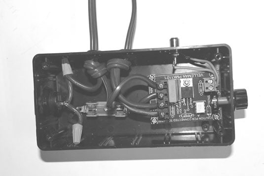
Guess what — you're almost done! The figure shows the project with all the parts assembled.The color organ is almost finished.
- Attach the knob to the potentiometer shaft protruding from the box.
Use a small, flat screwdriver to tighten the set screw on the knob.
- Place the lid over the project box and secure it with the provided screws. Now you really are done!