


The previous sketch showed you how to use a digitalRead to read either on or off, but what if you want to handle an analog value such as a dimmer switch or volume control knob?
For this project, you need
An Arduino Uno
A breadboard
A 10k ohm variable resistor
An LED
Jump wires
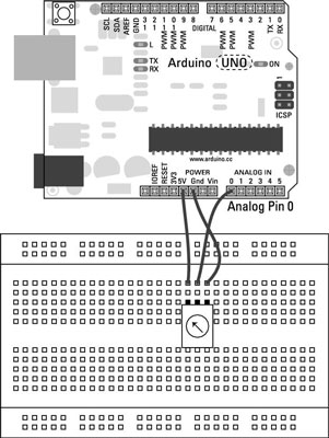
You see the layout for this circuit. You need an LED and a resistor for your output, and a variable resistor for your input.
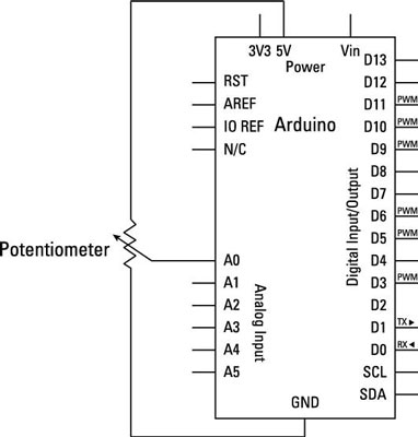
The variable resistor has power and ground connected across opposite pins, with the central pin providing the reading. To read the analog input, you need to use the special set of analog input pins on the Arduino board.
It’s also worth noting that if you were to swap the polarity (swap the positive and negative wires) of the resistor, you would invert the direction of the potentiometer. This can be a quick fix if you find that you’re going in the wrong direction.
Build the circuit and upload the code from File→Examples→03.Analog→AnalogInput.
/*
 Analog Input
 Demonstrates analog input by reading an analog sensor on analog pin 0 and
 turning on and off a light emitting diode(LED) connected to digital pin 13.
 The amount of time the LED will be on and off depends on
 the value obtained by analogRead().
 The circuit:
 * Potentiometer attached to analog input 0
 * center pin of the potentiometer to the analog pin
 * one side pin (either one) to ground
 * the other side pin to +5V
 * LED anode (long leg) attached to digital output 13
 * LED cathode (short leg) attached to ground
 * Note: because most Arduinos have a built-in LED attached
 to pin 13 on the board, the LED is optional.
 Created by David Cuartielles
 modified 30 Aug 2011
 By Tom Igoe
 This example code is in the public domain.
 http://arduino.cc/en/Tutorial/AnalogInput
 */
<b>int</b> sensorPin = A0; // select the input pin for the potentiometer
<b>int</b> ledPin = 13;  // select the pin for the LED
<b>int</b> sensorValue = 0; // variable to store the value coming from the sensor
void setup() {
 // declare the ledPin as an OUTPUT:
 pinMode(ledPin, OUTPUT);
}
void loop() {
 // read the value from the sensor:
 sensorValue = analogRead(sensorPin);
 // turn the ledPin on
 digitalWrite(ledPin, <b>HIGH</b>);
 // stop the program for <sensorValue> milliseconds:
 <b>delay</b>(sensorValue);
 // turn the ledPin off:
 digitalWrite(ledPin, LOW);
 // stop the program for for <sensorValue> milliseconds:
 <b>delay</b>(sensorValue);
}
After the sketch is uploaded, turn the potentiometer. The result is an LED that blinks slower or faster depending on the value of the potentiometer. You can add another LED between pin 13 and GND to improve the effect of this spectacle.
If you don’t see anything lighting up, double-check your wiring:
Make sure that you’re using the correct pin number for your variable resistor.
Check that your LED is the correct way around, with the long leg in pin 13 and the short leg in GND.
Check the connections on the breadboard. If the jump wires or components are not connected using the correct rows in the breadboard, they will not work.

