

Often, the best way to get acquainted with a new working platform, such as the BeagleBone, is to light up and turn off an LED on command. To do so, you set a GPIO (general purpose input/output) as output; you want to control the state of a component.
Wiring the circuit for an LED
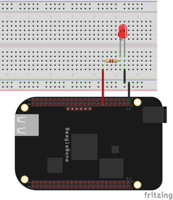
First, you set up the circuitry. Use the following steps to wire your circuit. For the locations of the pins used in the following steps, refer to this figure:

Turn off the BeagleBone.
Before plugging things into the BeagleBone, it’s generally a good idea to shut it down and remove the power source from it.
Power up the breadboard.
Using a jumper wire, connect the BeagleBone’s 3.3V source — pins 3 or 4 on header P9 — to the breadboard’s positive track.
Set up your ground.
Connect the BeagleBone’s GND pin —for example, pins 1 and 2 on both headers — to the breadboard’s negative track.
Connect a GPIO pin to the board.
This example uses GPIO 40 — pin 14 on the P9 header. Use a jumper to connect it to a vertical row on your breadboard.
Connect a resistor.
Without a resistor, an LED burns up easily. A 220 or 470 resistor should drop enough voltage without reducing the LED’s brightness too much. Connect the resistor to the jumper you pulled from pin 14, effectively connecting the resistor to GPIO 40.
Connect the LED.
Connect the LED’s negative leg — the cathode, which is usually the shorter leg — to the breadboard’s negative track where you connected ground in Step 3. Connect the positive leg — the anode — to the resistor.
In the circuit you’ve just built the power comes from GPIO 40 rather than a battery, which you turn on and off by writing into the command prompt.
In Step 2, you connect the BeagleBone’s 3.3V pin to the breadboard. In reality, for this specific project, making that connection serves no purpose. It’s generally good practice, however, to always have the horizontal tracks on your breadboard powered with a constant voltage and with a circuit ground.
If you were to connect the resistor to the positive rail on your breadboard, the LED would light up, but you’d have no control over it. Feel free to try it out!
Controlling the GPIO
Because pin 14 is already a GPIO pin by default, you can set it as output. After you’ve done that, you can easily control whether you want the LED to be on or off by setting the pin to HIGH or LOW, respectively.
You need to be logged in as the root user to access the GPIOs. If you’re currently logged in as debian, you can easily change to root as follows:
debian@beaglebone:~$ <b>sudo su</b>
On the command line, after connecting to your BeagleBone, change to the gpio directory with the following command:
root@beaglebone:~# <b>cd /sys/class/gpio</b>
If you list the contents of this directory, you can see that gpio40 isn’t there:
root@beaglebone:/sys/class/gpio# <b>ls</b>
export  gpiochip0  gpiochip32  gpiochip64  gpiochip96  unexport
You have to export it first by writing in the export file, which creates a folder containing files that can be altered to control the pin’s state. On the command line, type the following:
root@beaglebone:/sys/class/gpio# <b>echo 40 > export</b>
root@beaglebone:/sys/class/gpio# <b>ls</b>
export  gpio40  gpiochip0  gpiochip32  gpiochip64  gpiochip96  unexport
To control the pin’s state, change to the newly created gpio40 directory:
root@beaglebone:/sys/class/gpio# <b>cd gpio40</b>
root@beaglebone:/sys/class/gpio/gpio40# <b>ls</b>
active_LOW  direction  edge  power  subsystem  uevent  value
The direction file defines whether this GPIO pin functions as an input or output pin. Because you want to control its state by writing into it, your pin is supposed to be an output:
root@beaglebone:/sys/class/gpio/gpio40# echo out > direction
The value file holds the value of the GPIO: HIGH (1) or LOW (0). Thus, to turn the LED on, enter the following command:
root@beaglebone:/sys/class/gpio/gpio40# <b>echo 1 > value</b>
Now your LED should be on:
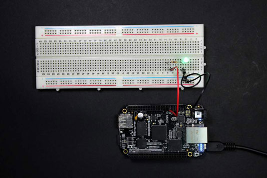
If the LED seems dim, try a lower resistance value. Do not go lower than 220, though.
To turn it off, use the following command:
root@beaglebone:/sys/class/gpio/gpio40# <b>echo 0 > value</b>
When you’re done with a pin, it’s often a good idea to unexport it so that it becomes available for different purposes. You unexport the pin by writing into the unexport file. The following succession of commands unexports gpio40 and shows that its directory has been eliminated.
root@beaglebone:/sys/class/gpio/gpio40# <b>cd ..</b>
root@beaglebone:/sys/class/gpio# <b>ls</b>
export  gpio40  gpiochip0  gpiochip32  gpiochip64  gpiochip96  unexport
root@beaglebone:/sys/class/gpio# <b>echo 40 > unexport</b>
root@beaglebone:/sys/class/gpio# <b>ls</b>
export  gpiochip0  gpiochip32  gpiochip64  gpiochip96  unexport
If you’re successful in controlling the LED, you may have just taken your first big step into digital electronics. Although lighting up an LED may not seem like much, the concept behind it is pretty much the same as controlling a motor, a buzzer, or an LCD screen!

