
Voltages across each device in a circuit can be described using node-voltage analysis (NVA). Node-voltage analysis reduces the number of equations you have to deal with when performing circuit analysis. Key ingredients of NVA include node voltages and reference nodes.
When a voltage source is connected to a node, you end up with fewer unknown node voltage equations because one of the node voltages is given in terms of the known voltage source. Here’s how the node voltages compare if you have a voltage source:
If the negative terminal of the voltage source is connected to a reference node, then the voltage of the node connected to the positive terminal of the voltage source has to be equal to the source voltage.
If the voltage source terminals are connected to two nonreference nodes, then the difference between the two node voltages is simply the source voltage. So if you know one node voltage, you get the other by adding or subtracting the source voltage to or from the known node voltage.
If you’re more comfortable dealing with current sources, you can perform a source transformation by replacing the voltage source and resistors connected in series with an equivalent current source and resistors connected in parallel.
Here is a circuit that shows that the negative terminal of a voltage source is usually given as 0 volts. As you can see, Circuit A has two voltage sources and three nonzero nodes. Through source transformation, you can transform the circuit into Circuit B, which has only one nonreference node.
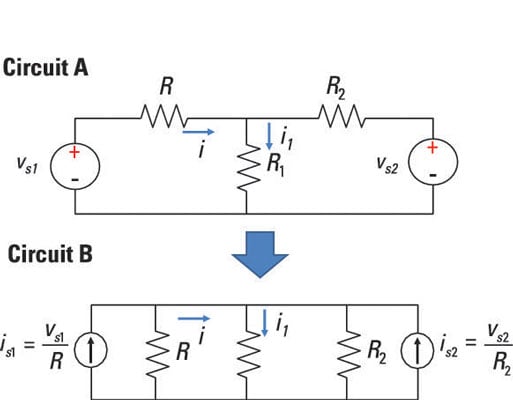
When you apply node-voltage analysis in Circuit B, you wind up with the following equation:
You get the same result using source transformation by noting that VA = Vs1 and VC = vs2. The next example illustrates the technique by relating the node voltages to the voltage source.
Sometimes you encounter circuits with two voltage sources that don’t have a common node. One voltage source is connected to a reference node, and the other voltage source has terminals connected to nonreference nodes, as shown here in this sample circuit.
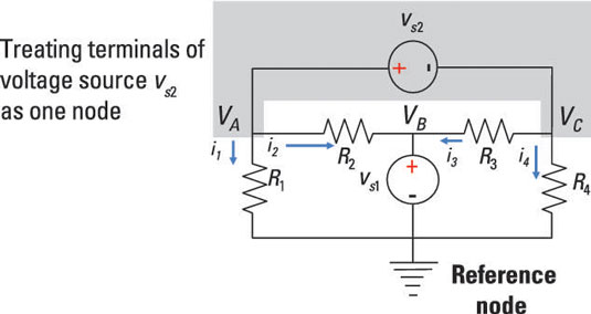
Consider the voltage source at the top of the sample circuit. Currents i1 through i4 leave and enter through the negative and positive terminals of vs2, which leads to the following KCL equation:
You can express these node voltages in the KCL equation in the following expression:
The source voltage vs1 at Node B is connected to a reference node, which means that
Because vs2 is connected at Nodes A and C, the voltage across vs2 is the difference between the node voltages at these nodes:
Replace VB and VC in the KCL equation to get the following expression:
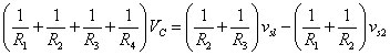
Put the source voltages on one side of the equation, which gives you
This equation now has one node voltage term.
Now, suppose the desired output voltage is the voltage across resistor R4, connected to VC. Substitute VC + vs2 for VA into the preceding equation:
Now simplify the equation:
Now you have one equation with the node voltage VC. This equation is easily solvable using algebra after you plug in some numbers for the resistors and voltage sources.