Circuit analysis techniques in the s-domain are powerful because you can treat a circuit that has voltage and current signals changing with time as though it were a resistor-only circuit. That means you can analyze the circuit algebraically, without having to mess with integrals and derivatives. Here you learn how to apply voltage and current divider methods in the s-domain.
Applying voltage division with series circuits
You can put voltage divider techniques to work when dealing with series circuits. To use voltage division in the s-domain, you simply replace the resistors with the impedances of devices connected in series. The following voltage divider equation is for three passive devices in a series circuit:
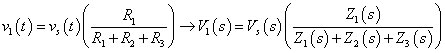
The output voltage V1(s) is based on the voltage source VS(s) and on the ratio of the desired impedance Z1(s) to the total impedance.
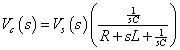
This illustrates the voltage divider for a series circuit for zero initial conditions: iL(0) = 0 and vC(0) = 0. You can find the output transform of the capacitor voltage using the voltage divider equation:
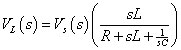
In a similar way, the voltage transform across the inductor is
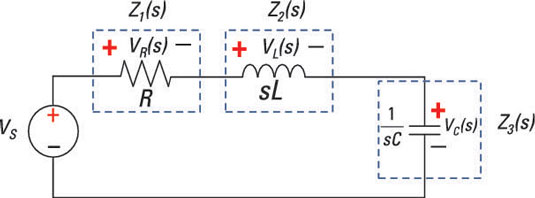
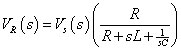
And the voltage transform across the resistor is
That’s all there is to it. You may need to do more algebraic gymnastics to simplify other circuits, but you still don’t need calculus. To get back to a time-domain description, you need to do a partial fraction expansion; then you look up the inverse Laplace transforms in this table.
In many cases, you just want to predict what the output is when you’re given a particular input. When you know the transfer function, which is the ratio between the output transform and the input transform, you can multiply the transfer function by the input voltage to find the output. As a result, you can rewrite the transform of the capacitor voltage as a ratio of polynomials:
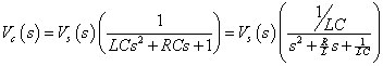
The denominator is simply a quadratic equation, and the roots of the equation shape the circuit behavior.
Similarly, you can rewrite the transform of the resistor and inductor voltages as a ratio of polynomials.
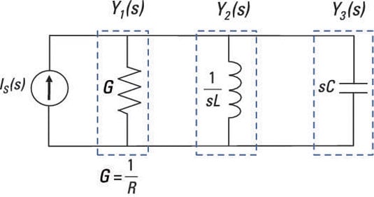
Turning to current division for parallel circuits
To use current division for parallel circuits having passive devices, all you have to do in the s-domain is replace the conductances with admittances. The following current divider equation is for three passive devices connected in parallel:
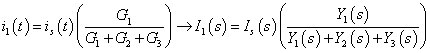
The output current I1(s) is based on the current source IS(s) and the ratio of the desired admittance Y1(s) to the total admittance.
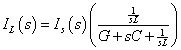
This illustrates the current divider technique for a parallel circuit for zero initial conditions: iL(0) = 0 and vC(0) = 0. You can find the output transform of the inductor current using the current divider equation:
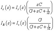
In the same way, you get the transform of the capacitor and conductance (or resistor) currents using the current divider technique:
Note that the results resemble the form for series circuits using voltage divider techniques. Neat and simple in the s-domain — thank you, Pierre Laplace!