
Thévenin’s and Norton’s theorems can be used to analyze complex circuits by focusing on the source and load circuits. One application of Thévenin’s and Norton’s theorems is to calculate the maximum power for a load circuit.
The power p coming from the source circuit to be delivered to the load depends on both the current i flowing through the load circuit and the voltage v across the load circuit at the interface between the two circuits.
The maximum power theorem states that for a given source with a fixed Thévenin resistance RT, the maximum power delivered to a load resistor RL occurs when the RL is matched or equal to RT:
pmax when RL = RT
Mathematically, the power is given by the following expression:
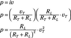
p = iv
The source circuit delivers maximum voltage when you have an open-circuit load. Because zero current flows through the open-circuit load, zero power is delivered to the load. Mathematically, the power poc delivered to the open-circuit load is
poc = iv = 0 ∙ v = 0
On the other hand, the source circuit delivers maximum current when you have a short-circuit load. Because zero voltage occurs across the short-circuit load, zero power is delivered to the load. Mathematically, the power psc delivered to the short-circuit load is
psc = iv = i ∙ 0 = 0
So what’s the maximum power punch delivered for a given load resistance? Using either the Thévenin or Norton approach allows you to find the maximum power delivered to the load circuit.
To see how to determine the maximum power, look at the resistor arrangements for both the source and load circuits in this sample circuit. In this figure, the source circuit is the Thévenin equivalent, and the load resistor is a simple but adjustable resistor.
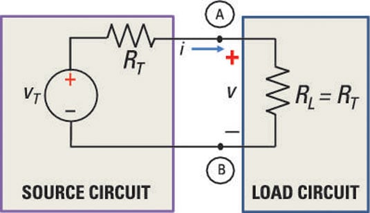
Intuitively, you know that maximum power is delivered when both the current and voltage are maximized at the interface Terminals A and B.
Using voltage division, the voltage v across the interface at A and B is
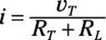
In the sample circuit, the connected circuit between the source and load is a series circuit. The current i flows through each of the resistors, so
Substituting the values of v and i into the power equation, you wind up with the following power equation:
Determining the maximum power delivered to the load means taking the derivative of the preceding equation with respect to RL and setting the derivative equal to zero. Here’s the result:
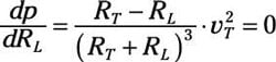
This equation equals zero when the numerator is zero. This occurs when RL = RT. Therefore, maximum power occurs when the source and load resistances are equal or matched.