Simple electronic circuits can have as little as two components. Most electronic circuits will have additional components. There are hundreds of different types of electronic components, and each has its own unique schematic diagram symbol. Fortunately, you need to know only a few basic symbols and labels to get you started.
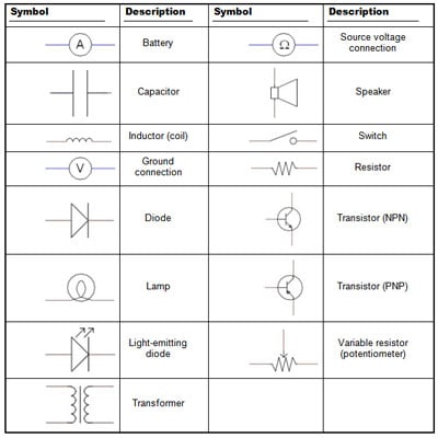
Note that when used in an actual circuit diagram, the symbols are often rotated.
A symbol alone is not usually enough information to completely identify an electronic component in a schematic diagram. Further information is usually included with text that's placed adjacent to the symbol. This additional information usually includes the following:
Reference identifier: Each component is usually labeled with a letter that designates the type of component followed by a number that helps identify each component of the same type. For example, if a circuit has four resistors, the resistors are identified as R1, R2, R3, and R4.
Letter Meaning R Resistor C Capacitor L Inductor D Diode LED Light-emitting diode Q Transistor SW Switch IC Integrated circuit Value or part number: For components such as resistors and capacitors, the value is given in ohms (for resistors) and microfarads (for capacitors). Thus, a 470 Ω resistor would have the number 470 next to it, and a 100 μF capacitor would have the number 100 next to it.
The letters K and M are used to denote thousands and millions. For example, a 10,000 Ω resistor is identified as 10K in a schematic.
Components such as diodes, transistors, and integrated circuits don't have values; instead, they have manufacturer's part numbers. Thus, you might find a part number such as 1N4001 (for a diode), 2N2222 (for a transistor), or 555 (for an integrated circuit, IC) next to one of these components.
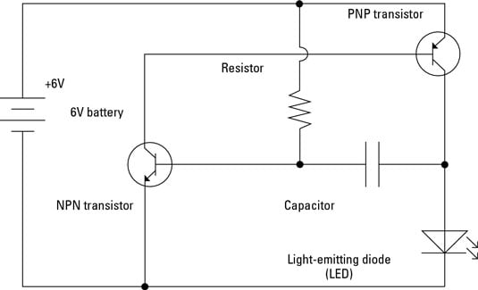
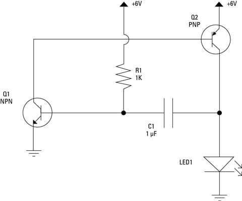 A schematic diagram with parts labeled.
In some cases, the value or part number is omitted from the schematic diagram itself and instead included in a separate parts list that identifies the value or part number of each referenced part that appears in the schematic. Then, to find the value or part number of a particular component, you look up the component by its reference identifier in the parts list.
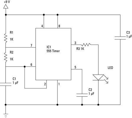
One important symbol that isn't shown is the symbol for an IC (integrated circuit). ICs are small assemblies that usually have multiple leads, called pins, which connect to various parts of the circuit contained within the assembly. Some ICs have as few as six or eight pins; others have dozens or even hundreds. These pins are numbered, beginning with pin 1.
The most common way to depict an integrated circuit in a schematic diagram is as a simple rectangle with leads coming out of it to depict the various pins. The arrangement of the pins in the schematic diagram doesn't necessarily correspond to the physical arrangement of pins on the IC itself.
Instead, the pins are positioned to provide for the simplest circuit paths in the diagram. The pins in the diagram are numbered to indicate the correct pin to use.
A popular IC called a 555 timer IC is used to make an LED flash. The 555 has eight pins, and the schematic calls for connections on all eight. However, the pins in the diagram are arranged in a manner that simplifies the connections to be made to the pins.
In an actual 555 IC, the pins are arranged in numerical order on either side of the IC, with pins 1 through 4 on one side and pins 5 through 8 on the other side.