RLC series band-pass filter (BPF)
You can get a band-pass filter with a series RLC circuit by measuring the voltage across the resistor VR(s) driven by a source VS(s). Start with the voltage divider equation: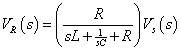
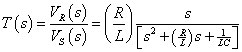
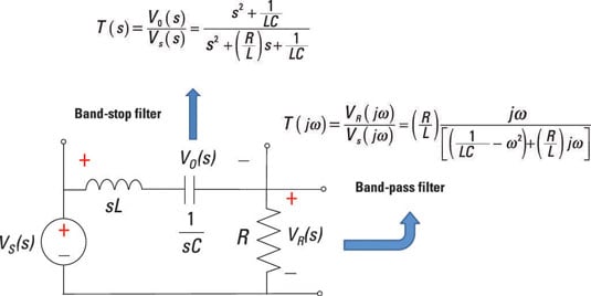
With some algebraic manipulation, you obtain the transfer function, T(s) = VR(s)/VS(s), of a band-pass filter:
Plug in s = jω to get the frequency response T(jω):
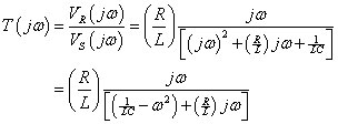
The T(jω) reaches a maximum when the denominator is a minimum, which occurs when the real part in the denominator equals 0. In math terms, this means that
The frequency ω0 is called the center frequency.
The cutoff frequencies are at the –3 dB half-power points. The –3 dB point occurs when the real part in the denominator is equal to Rω/L:
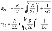
You basically have a quadratic equation, which has four roots due to the plus-or-minus sign in the second term. The two appropriate roots of this equation give you cutoff frequencies at ωC1 an ωC2:
The bandwidth BW defines the range of frequencies that pass through the filter relatively unaffected. Mathematically, it’s defined as
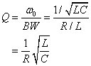
Another measure of how narrow or wide the filter is with respect to the center frequency is the quality factor Q. The quality factor is defined as the ratio of the center frequency to the bandwidth:
The RLC series circuit is narrowband when Q >> 1 (high Q) and wideband when Q << 1 (low Q). The separation between the narrowband and wideband responses occurs at Q = 1. Here is a series band-pass circuit and gain equation for an RLC series circuit.
The frequency response is shaped by poles and zeros. For this band-pass filter, you have a zero at ω = 0. You start with a gain slope of +20 dB. You hit a cutoff frequency at ωC1, which flattens the frequency response until you hit another cutoff frequency above ωC2, resulting in a slope of –20 dB/decade.
RLC series band-reject filter (BRF)
You form a band-reject filter by measuring the output across the series connection of the capacitor and inductor. You start with the voltage divider equation for the voltage across the series connection of the inductor and capacitor: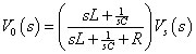
You can rearrange the equation with some algebra to form the transfer function of a band-reject filter:
When you plug in s = jω, you have poles and zeros shaping the frequency response. For the band-reject filter, you have a double zero at 1 / √LC.
Starting at ω = 0, you have a gain of 0 dB. You hit a pole at ωC1, which rolls off at –20 dB/decade until you hit a double zero, resulting in a net slope of +20 dB/decade. The frequency response then flattens out to a gain of 0 dB at the cutoff frequency ωC2. You see how the poles and zeros form a band-reject filter.