
Use op amp circuits to build mathematical models that predict real-world behavior.The mathematical uses for signal processing include noninverting and inverting amplification. One of the most important signal-processing applications of op amps is to make weak signals louder and bigger.
Analyze a basic noninverting op amp circuit
The following example shows how the feedback affects the input-output behavior of an op amp circuit. Consider this sample circuit, which first shows the input connected to the noninverting input. You have a feedback path from the output circuit leading to the inverting input.
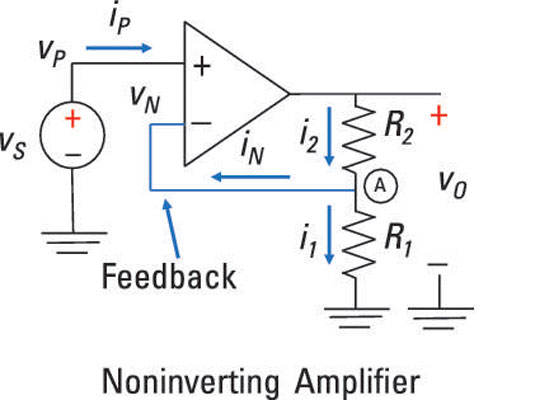
The voltage source vS connects to the noninverting input vP:
You gotta first find the voltage at the inverting input so you can figure out how the input and output voltages are related. Apply Kirchhoff’s current law (KCL) at Node A between resistors R1 and R2.
Recall that Kirchoff’s current law (KCL) says the sum of incoming currents is equal to the outgoing currents.
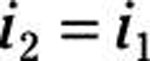
Applying KCL gives you:
At the output side of the op amp, the inverting current iN is equal to zero because you have infinite resistance at the inverting input. This means that all the current going through resistor R2 must go through resistor R1. If the current is the same, R1 and R2 must be connected in series, giving you
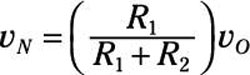
Because resistors R1 and R2 are connected in series, you can use voltage division. Voltage division gives you the voltage relationship between the inverting input vN and output vO:
The inverting input vN and noninverting input vP are equal for ideal op amps. So here’s the link between the input source voltage vS and output voltage vO:
You now have the ratio of the voltage output to the input source:
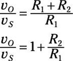
You just made the input voltage vS larger by making sure the ratio of the two resistors is greater than 1. To make the input signal louder, the feedback resistor R2 should have a larger value than input resistor R1. Piece of cake! For example, if R2 = 9 kΩ and R1 = 1 kΩ, then you have the following output voltage:
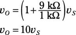
You’ve amplified the input voltage by ten. Awesome!
Analyze a unique noninverting op amp: a voltage follower
A special case of the noninverting amplifier is the voltage follower, in which the output voltage follows in lock step with whatever the input signal is. In the voltage follower shown here, vS is connected to the noninverting terminal.
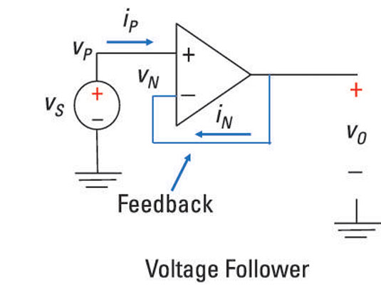
You can express this idea as
You also see that the output vO is connected to the inverting terminal, so
An ideal op amp has equal noninverting and inverting voltage. This means that the preceding two equations are equal. In other words
You can also view the voltage follower as a special case of the noninverting amplifier with a gain of 1, because the feedback resistor R2 is zero (a short circuit) and resistor R1 is infinite (open circuit):
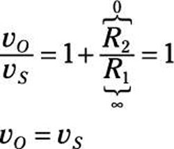
The output voltage vO is equal to the input source voltage vS. The voltage gain is 1 where the output voltage follows the input voltage. But a piece of wire gives a gain of 1, too, so what good is this circuit? Well, the voltage follower provides a way to put together two separate circuits without having them affect each other.
When they do affect each other in a bad way, that’s called loading. A voltage follower solves the loading problem.